CCIE Data: Lab Blueprint 1.1c Implementing Port Channels
CCIE Data Center Lab Blueprint
1.1c Implementing Port Channels
ConfigBytes #2
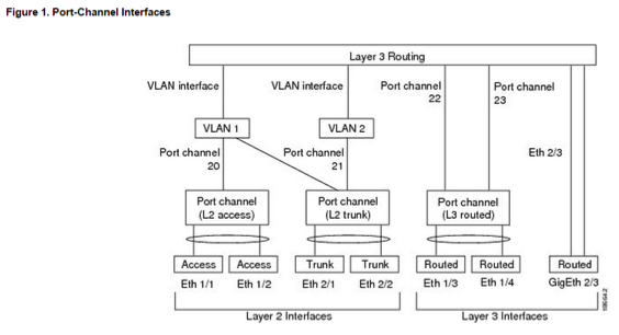
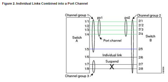
Port Channels
A port channel bundles physical links into a channel group to create a single logical link that provides the aggregate bandwidth of up to 16 physical links. If a member port within a port channel fails, the traffic previously carried over the failed link switches to the remaining member ports within the port channel.
- F and M series line card port members cannot be mixed into a port-channel.
- On a single switch, the port-channel compatibility parameters (SPEED,DUPLEX,ETC) must be the same among all the port-channel members on the physical switch.
- Use port-channels for resiliency and aggregation of throughput.
- 8 member links per port-channel prior to 5.1
- NXOS 5.1> 16
- member links
- L2 & L3 port-channels available on NXOS
- Port-channel interface ID range 1-4096
- Configuration changes made to logical port-channel interface is inherited by the individual member interfaces.
- You can use static port channels, with no associated aggregation protocol, for a simplified configuration. For more flexibility, you can use LACP. When you use LACP, the link passes protocol packets. You cannot configure LACP on shared interfaces.
- PAgP is NOT supported on NXOS
- The port channel is operationally up when at least one of the member ports is up and that port’s status is channeling. The port channel is operationally down when all member ports are operationally down.
| Note | After a Layer 2/3 port becomes part of a port channel, all configurations must be done on the port channel; you can no longer apply configurations to individual port-channel members. you must apply the configuration to the entire port channel. |
Compatibility Requirements
When you add an interface to a channel group, the software checks certain interface attributes to ensure that the interface is compatible with the channel group. For example, you cannot add a Layer 3 interface to a Layer 2 channel group. The Cisco NX-OS software also checks a number of operational attributes for an interface before allowing that interface to participate in the port-channel aggregation.
The compatibility check includes the following operational attributes:
- (Link) speed capability
- Access VLAN
- Allowed VLAN list
- Check rate mode
- Duplex capability
- Duplex configuration
- Flow-control capability
- Flow-control configuration
- Layer 3 ports—Cannot have subinterfaces
- MTU size
- Media type, either copper or fiber
- Module Type
- Network layer
- Port mode
- SPAN—Cannot be a SPAN source or a destination port
- Speed configuration
- Storm control
- Tagged or untagged
- Trunk native VLAN
Use the show port-channel compatibility-parameters command to see the full list of compatibility checks that the Cisco NX-OS uses.
You can only add interfaces configured with the channel mode set to on to static port channels, and you can only add interfaces configured with the channel mode as active or passive to port channels that are running LACP. You can configure these attributes on an individual member port. If you configure a member port with an incompatible attribute, the software suspends that port in the port channel.
Alternatively, you can force ports with incompatible parameters to join the port channel if the following parameters are the same:
- (Link) speed capability
- Speed configuration
- Duplex capability
- Duplex configuration
- Flow-control capability
- Flow-control configuration
Port Channel Load Balancing
- Port channels provide load balancing by default
- Port-channel load balancing uses L2 (MAC), L3 (IP), or L4 (port) to select the link
- SRC or DST or both SRC and DST
- Per switch (global) or per module. Per module takes precedence over per switch
- L3 default is SRC/DST IP address
- L2/non-IP default is SRC/DST MAC address
- 6.0(1) for F series line card L2 load balancing
- Must be in the default VDC to configure
You can configure load balancing either by the entire system or by specific modules, regardless of the VDC. The port-channel loadbalancing is a global setting across all VDCs.
If the ingress traffic is Multiprotocol Label Switching (MPLS) traffic, the software looks under the labels for the IP address on the packet.
The load-balancing algorithms that use port channels do not apply to multicast traffic. Regardless of the load-balancing algorithm you have configured, multicast traffic uses the following methods for load balancing with port channels:
- Multicast traffic with Layer 4 information—Source IP address, source port, destination IP address, destination port
- Multicast traffic without Layer 4 information—Source IP address, destination IP address
- Non-IP multicast traffic—Source MAC address, destination MAC address
| Note | Devices that run Cisco IOS can optimize the behavior of the member ports. ASICs if a failure of a single member occurred if you enter the port-channel hash-distribution command. The Cisco Nexus 7000 Series device performs this optimization by default and does not require or support this command. |
Cisco NX-OS Release 6.1(3) supports a new Result Bundle Hash (RBH) mode to improve load balancing on port-channel members on Cisco Nexus 7000 M Series I/O XL modules and on F Series modules. With the new RBH modulo mode, the RBH result is based on the actual count of port-channel members.
LACP
- Feature disabled by default. Must be enable feature first
- Up to 16 active interfaces with 5.1>
- Active 8, 8 Standby before 5.1
- Modes are active, passive, or ON (static port-channel NO LACP)
- ON mode or static port channels is the DEFAULT mode
Both the passive and active modes allow LACP to negotiate between ports to determine if they can form a port channel based on criteria such as the port speed and the trunking state.
The passive mode is useful when you do not know whether the remote system, or partner, supports LACP.
Ports can form an LACP port channel when they are in different LACP modes if the modes are compatible as in the following examples:
- A port in active mode can form a port channel successfully with another port that is in active mode.
- A port in active mode can form a port channel with another port in passive mode.
- A port in passive mode cannot form a port channel with another port that is also in passive mode, because neither port will initiate negotiation.
- A port in on mode is not running LACP and cannot form a port channel with another port that is in active or passive mode.
LACP System ID is the combination of the LACP System Priority and MAC Address. Value of system priority is 1-32,768. Lower priority value = higher system priority. 1 being the highest priority.
Port Priority values are from 1-65535. Port priority + port number (interface ID) = LACP Port ID
Lower PortID value = higher priority to be chosen for forwarding/active vs. standby links. Default port priority is 32,768
Prerequisites for Port Channeling
Port channeling has the following prerequisites:
- You must be logged onto the device.
- If necessary, install the Advanced Services license and enter the desired VDC.
- All ports in the channel group must be in the same VDC.
- All ports for a single port channel must be either Layer 2 or Layer 3 ports.
- All ports for a single port channel must meet the compatibility requirements. See the “Compatibility Requirements” section for more information about the compatibility requirements.
- You must configure load balancing from the default VDC.
Guidelines and Limitations
Port channeling has the following configuration guidelines and limitations:
- The LACP port-channel minimum links and maxbundle feature is not supported for host interface port channels.
- You must enable LACP before you can use that feature.
- You can configure multiple port channels on a device.
- Do not put shared and dedicated ports into the same port channel. (See “Configuring Basic Interface Parameters,” for information about shared and dedicated ports.)
- For Layer 2 port channels, ports with different STP port path costs can form a port channel if they are compatibly configured with each other. See the “Compatibility Requirements” section for more information about the compatibility requirements.
- In STP, the port-channel cost is based on the aggregated bandwidth of the port members.
- After you configure a port channel, the configuration that you apply to the port channel interface affects the port channel member ports. The configuration that you apply to the member ports affects only the member port where you apply the configuration.
- LACP does not support half-duplex mode. Half-duplex ports in LACP port channels are put in the suspended state.
- You must remove the port-security information from a port before you can add that port to a port channel. Similarly, you cannot apply the port-security configuration to a port that is a member of a channel group.
- Do not configure ports that belong to a port channel group as private VLAN ports. While a port is part of the private VLAN configuration, the port channel configuration becomes inactive.
- Channel member ports cannot be a source or destination SPAN port.
- You cannot configure the ports from an F1 and an M1 series linecard in the same port channel because the ports will fail to meet the compatibility requirements.
- You cannot configure the ports from an M1 and M2 series linecard in the same port channel.
- You cannot configure the ports from an F2e and an F3 series linecard in the same port channel because the ports will fail to meet the compatibility requirements.
- Beginning with Cisco NX-OS Release 5.1, you can bundle up to 16 active links into a port channel on the F1 series linecard.
- F1 Series modules do not support load balancing of non-IP traffic based on a MAC address. If ports on an F1 Series module are used in a port channel and non-IP traffic is sent over the port channel, Layer 2 traffic might get out of order.
- Only F Series and the XL type of M Series modules support the RBH modulo mode.
Feature History for Configuring Port Channels
| Feature Name | Release | Feature Information |
| Display policy errors on interfaces and VLANs | 6.2(2) | Added the show interface status error policy command. |
| Prevent traffic-drop during bi-directional flow on F2 or F2e modules | 6.2(2) | Added the asymmetric keyword to port-channel load-balance command to improve load balancing across port channels. |
| Result Bundle Hash load balancing | 6.1(3) | Support for the RBH modulo mode to improve load balancing across port channels. |
| Minimum links for FEX fabric port channel | 6.1(3) | This feature was introduced. |
| Port channels hash distribution | 6.1(1) | Support for port channel hash distribution fixed and adaptive mode. |
| Load-balancing supports F2 modules | 6.0(1) | Added support for F2 modules on load-balancing across port channels. |
| Port channels | 5.2(1) | Support increased to 528 port channels. |
| Minimum links and Maxbundle for LACP | 5.1(1) | This feature was introduced. |
| Port channels | 4.2(1) | Support increased to 256 port channels. |
| Port channels | 4.0(1) | This feature was introduced. |
Example Lab Question and Configuration
Port Channel Task
Assuming that more links will be added later, with the desire for minimal traffic disruption (LACP), configure the following:
Configure trunking on port channel 100 from N7K1 to UCS FI-A, and ensure that the same port channel number is used later from the UCS side.
interface Ethernet1/22
switchport
switchport mode trunk
switchport trunk allowed vlan 100,200,300,400,500
channel-group 100 mode active (LACP)
no shutdown
Configure trunking on port channel 200 from N7K1 to UCS FI-B, and ensure that the same port channel number is used later from the UCS side.
interface Ethernet1/24
switchport
switchport mode trunk
switchport trunk allowed vlan 100,200,300,400,500
channel-group 200 mode active (LACP)
no shutdown
Ensure that both of these port channels transition immediately to a state of
forwarding traffic.
“Int port-channel 100” & “Int port-channel 200”
“spanning-tree port type edge trunk”
Ensure that the N7K1 is the primary device in LACP negotiation. Ensure that the hashing algorithm takes L3 and L4 for both source and destination into account.
“lacp system-priority 1” Lower system priority value = higher priority
1-32768
“port-channel load-balance src-dst ip-l4port”
Trunk only previously created VLANs 100,200,300,400,500 southbound from N7K1 to both FIs.
Verify with “Show port-channel summary”
DocCD: http://www.cisco.com/c/en/us/td/docs/switches/datacenter/sw/nx-os/interfaces/configuration/guide/b-Cisco-Nexus-7000-Series-NX-OS-Interfaces-Configuration-Guide/b-Cisco-Nexus-7000-Series-NX-OS-Interfaces-Configuration-Guide-6x_chapter_0111.html